Overview
The power subsystem is one of the most important aspects of ION since continuous and stable power is needed by many subsystems. Power is supplied by two means: solar cells and lithium-ion batteries. The Solar Cells supply power to charge the lithium-ion batteries and to the satellite. The Charger takes power from the solar cells and charges batteries as needed. The Batteries supply power to ION when on the dark side of the earth and the Voltage Bus regulates the DC/DC converters that will output the required voltages for each subsystem.
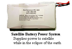
Batteries
Roughly one-third of IONs operational lifetime will be spent in eclipse. Since, during this period, ION will not see the sun, the solar cells will not generate power. ION will rely on its batteries during this period. The batteries, therefore, act to fulfill a very important role within the whole system. As a result, choosing a good battery for ION is very important.
The worst-case scenario is the prime factor in determining if a particular solar cell is practical for use. Power consumption of all ION systems were calculated and then compared to estimates of power generated when the spacecraft-sun orientation (solar beta angle) was such that minimum power was produced. Twenty solar cells having an average efficiency of 27.5% and supplying 1W of power were selected. The cost of these cells are $300 per solar cell. The layout of each solar panel consists of five cells in series, one panel for each of the four 21.5x10 cm sides of ION. Each solar panel consists of a circuit board, five solar cells, copper inter-connectors, and epoxy. The best epoxy for our environmental conditions is controlled volatility electrically conductive epoxy . This method seems best, because these materials are made for low-pressure environments like high altitudes and space. This will also be easier than trying to soldier connections on to the back to the solar cells. The cells are extremely fragile, which makes handling the cells difficult.
Power Requirements The power requirements for the systems are broken down into the groups by the regulator they are connected to. This breaks up the power requirements into four different groups: 9.6 V regulator, the 5 V regulator, the 20 V regulator, and the unregulated bus. The groups are divided up like this, because the efficiencies of the regulators can then be taken into account. The 9.6 V regulator powers the transceiver and the magnetometer. The 20 V regulator provides power to the magnetometer set/reset circuit. The 5 V regulator supplies power to the processor, the PMT, and the CMOS camera. Finally the unregulated group supplies the thrusters and torque coils.
|
||||||||||||


 Solar Cells