|
Component |
Placement
Justification |
|
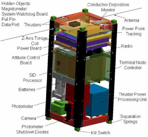
Photometer |
Positioned at the bottom
of the satellite, in order to face the
earth and take atmospheric readings. |
|
Photometer Shutdown Diodes |
Located next to the photometer facing in the
same direction. |
|
Camera |
Positioned at the bottom of the satellite, in
order to constantly face the and earth and take pictures of
it. |
|
Torque Coils |
One torque coil is mounted perpendicular to each axis for
proper attitude control. |
|
Batteries |
The batteries are the heaviest and largest object onboard,
as such they are located on one side as close to the
geometrical center as possible, minimizing both CG problems
and the occupied space. |
|
Antenna |
Located at the top of the satellite, which maximizes its
deployable length. |
|
Thruster Power Processing Unit |
This unit requires vibrational isolation and is mounted on
four legs, this required a firm mount on the bottom of the
satellite. |
|
Thrusters |
Four thrusters are located on opposite sides of the
satellite at opposite corners to maximize control ability. |
|
Separation Springs |
The feet are the only part of
CubeSats that contact other
CubeSats, so springs are located there to help separate the
satellites when deployed on orbit. |
|
Switches |
Switches are also located on the feet and will be depressed
in the PPOD, upon deployment they will open up and allow the
satellite to power up. |
|
Pull Pin |
The pull pin is located in the middle of the satellite, so
that it is inline with one of the windows on the PPOD. This
is a redundant switch that cuts power, and can be removed
via the window before launch. |
|
Power Board & Attitude Control Board |
These boards are mounted together horizontally to minimize
the occupied space. |
|
SID Processor |
Centrally located to minimize wire lengths. |
|
Power Point Tracking Board |
This board was sized to fit next to the antenna board to
maximize the space at the top of the satellite. |
|
Radio |
The radio board is mounted in the middle of the satellite as
close to the radio board as possible to minimize wire
lengths. |
|
Terminal Node Controller |
This board was located on an adjacent face to radio board
and the SID Processor to minimize wire lengths between the
three boards. |


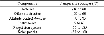 Three
stages of the mission affect the thermal control system (TCS):
the launch, the orbital placement by the launch vehicle, and the
final orbit. The launch vehicle will provide a temperature
adequate for the first two stages of this mission. The final
orbit determines which TCS must be used for each component. Each
component has its own operational temperature range. Even when
not operational, it is not advised to fall outside of the
operational temperature range for an extended amount of time.
Three
stages of the mission affect the thermal control system (TCS):
the launch, the orbital placement by the launch vehicle, and the
final orbit. The launch vehicle will provide a temperature
adequate for the first two stages of this mission. The final
orbit determines which TCS must be used for each component. Each
component has its own operational temperature range. Even when
not operational, it is not advised to fall outside of the
operational temperature range for an extended amount of time.